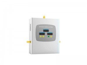
LED medical gas automatic manifold system is the latest development of our factory series of products, is the core unit of the medical central gas supply station. This series of the automatic manifold system by mechanical pressure difference valve automatic switching control, copper integration structure of dual-path design, stable pressure, and large flow. The automatic switch is flexible and can also be manual, the forward building of secondary voltage box provides steady inlet pressure, direct supply using the terminal. Under the working state, a gas feed, another way for standby. When the way air pressure is lowered to the predetermined minimum value, the control system can automatically switch to another road, alternating gas supply, the continuous supply of ward building, realize the uninterrupted supply of medical gases.
1.Description of the various components models and specifications
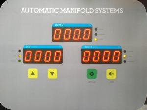
1.1 The setting of the LED automatic manifold system control panel
① Press and hold the setting key for 3 seconds, the two digital displays on the lower side are displayed: ID 0000, means the ID code of the control panel, and press the “Up” or “Down” key to modify the ID number of the control panel.
② Continue to tap the setting button, digital display P n-H 0.000 indicates the upper limit alarm value, press “up” key or “down” key to modify the upper limit alarm value.
③To continue to tap the setting key, digital display P n-L 000.0 indicates the lower limit alarm value of the outlet pressure, and the lower limit alarm value can be modified by pressing the “up” key or “down” key.
④To continue to tap the setting key, digital display P 1-L 0000 indicates the lower limit alarm value of the left cylinder pressure, and the lower limit alarm value can be modified by pressing the “up” key or “down” key.
⑤To continue to tap the setting key, digital display P 2-L 0000 indicates the lower limit alarm value of the right cylinder pressure, and the lower limit alarm value can be modified by pressing the “up” key or “down” key.
⑥The mute button can control the sound of the buzzer switch.
1.2 Instructions for pressure transmitter
Left and right pressure transmitter PCM300-25 monitoring range 0~ 25Mpa(250bar), input 24VDC, output 0~ 10V. The two pressure transmitters monitor the gas pressure of the left and right cylinders and transmit the pressure value signal to the control panel. The outlet pressure transmitter PCM300-1.6 monitoring range 0~1.6 MPa(16bar), input 24VDC, output 0~ 10. Its function is to monitor the pressure of the gas outlet port and transmits the pressure value signal value to the control panel.
1.3 Controller instructions
①The output pressure is “HIGH”, indicates output pressure exceeds pressure setting value
②The output pressure is “NORMAL”, indicates that the output pressure is between the lower limit and the upper limit
③Output pressure is “LOW”, indicates the output pressure is lower than the pressure lower limit set value
④The input pressure of the left bottle is “NORMAL”, indicating that the input pressure is above the pressure limit setting value
⑤The input pressure of the left bottle is “LOW”, indicating that the input pressure of the left bottle is lower than the pressure limit setting value, and the cylinder should be replaced
⑥The left bottle input pressure “WORKING” lamp indicates that the left side is working state
⑦The input pressure of the right bottle is “NORMAL”, indicating that the input pressure is higher than the pressure limit setting value
⑧The input pressure of the right bottle is “LOW”, indicating that the input pressure of the right bottle is lower than the pressure limit setting value, and the cylinder should be replaced
⑨The right cylinder input pressure “WORKING” lamp indicates that the right side is working state
⑩The upper digital tube and the indicator light indicate the output status; The left digital tube and indicator light indicates the work state of the left cylinder input; The right digital tube and indicator light indicates the status of the right cylinder input (see below 🙂
1.4 Control system
Real-time display and monitoring of gas input and output status; if meet the set value of the control panel logic will automatically switch to the other side, to achieve automatic electronic control switch, the other side automatically switches the same.
2.Gas path system operation instructions
(1). ① Automatic operation after connecting cylinders. Can adjust J1-1.6 and J2-1.6 adjust the output pressure to meet the demand of gas supply.
② Check whether the connection between two cylinders is reliable slowly opens the valve of each group of cylinders.
(2). The control cabinet J1 – 15, J2 – 15 pressure regulator has adjusted the output 1.3MPa, System is set to automatically switch status.
(3). Automatic switch control system D1, D2 controlled by the automatic switching controller, such as the left gas, when the output pressure below the set pressure, B11.6 signal to trigger electronic switch control system, power control D1 D1 D2 power D2 closed, open, right and left the road supply undervoltage alarm; when B2 1.6 air pressure below the set pressure, the B2 – 1.6 signal to trigger electronic switch control system, power control D2 D2 D1 make D1 power off, open the left turn left and right air supply; alternate work, Everfount to supply gas to the ward building. Standby gas should be replaced in a timely manner, without spare gas, the alarm will alarm, in the use of gas to replace a good standby gas before the alarm, the alarm is released.
3.Matters needing attention
(1). When the pressure gauge pressure value is greater than 1.8Mpa, or the safety valve exhaust, should immediately shut down the road into the gas source, at the same time open the other way gas, and then deal with the fault. After the failure to open the valve and then open the valve.
(2). Pressure gauges B2, B1 should be checked once a year, pay attention to ban oil.
(3). The automatic manifold system control box around is not allowed to open fires.
(4). All accessories and equipment in the gas supply system shall be prohibited from oil, and shall be responsible for the maintenance and repair of the equipment.
(5). This product appearance and so on with the technical innovation will be subject to change without notice.
4.Safe use rules
(1). Engaged in the gas pipeline, equipment maintenance, maintenance, and operation of personnel, must understand the nature of the gas, master the network process, and after the safety technology, operation and maintenance, and other rules of the examination, qualified to work independently.
(2). Gas cylinders used in gas cylinders should be in accordance with GB. The use of industrial gases in place of medical gases should be approved by the relevant departments.
(3). The valve must be operated slowly, found the valve leakage, should be excluded after the failure, and then use.
(4). All kinds of valves, sealing materials, instruments, and equipment used in the tracheal net must be approved by the professional department and can be used in the gas system. Instruments should be marked with “no oil” mark.
(5). The cylinder center gas station between the liquid tank near the non-open fires.
(6). The grounding device for the gas pipeline shall be inspected once every year before the rainy season, the grounding resistance should meet the YYO186-94 standard.
(7). All equipment operations should be prohibited oil, no oil gloves to be operated on.
(8). The automatic manifold system should be managed and maintained by the Medical Center gas supply system.